- 您现在的位置:买卖IC网 > Sheet目录3886 > PIC16C54C-04/SO (Microchip Technology)IC MCU OTP 512X12 18SOIC
2002 Microchip Technology Inc.
Preliminary
DS30453D-page 19
PIC16C5X
5.0
RESET
PIC16C5X devices may be RESET in one of the follow-
ing ways:
Power-On Reset (POR)
MCLR Reset (normal operation)
MCLR Wake-up Reset (from SLEEP)
WDT Reset (normal operation)
WDT Wake-up Reset (from SLEEP)
Table 5-1 shows these RESET conditions for the PCL
and STATUS registers.
Some registers are not affected in any RESET condi-
tion. Their status is unknown on POR and unchanged
in any other RESET. Most other registers are reset to a
“RESET state” on Power-On Reset (POR), MCLR or
WDT Reset. A MCLR or WDT wake-up from SLEEP
also results in a device RESET, and not a continuation
of operation before SLEEP.
The TO and PD bits (STATUS <4:3>) are set or cleared
depending on the different RESET conditions (Table 5-
1). These bits may be used to determine the nature of
the RESET.
Table 5-3 lists a full description of RESET states of all
registers. Figure 5-1 shows a simplified block diagram
of the On-chip Reset circuit.
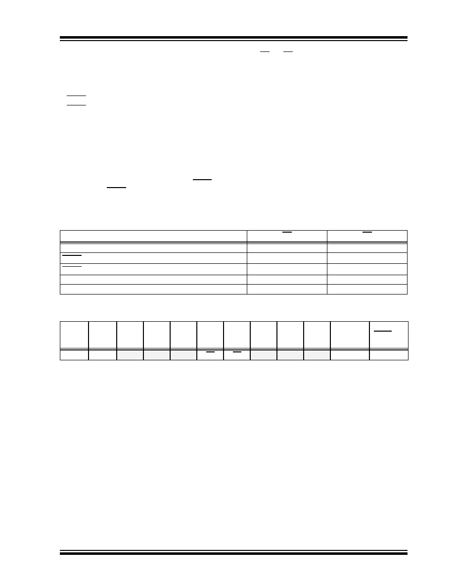
TABLE 5-1:
STATUS BITS AND THEIR SIGNIFICANCE
TABLE 5-2:
SUMMARY OF REGISTERS ASSOCIATED WITH RESET
Condition
TO
PD
Power-On Reset
11
MCLR Reset (normal operation)
uu
MCLR Wake-up (from SLEEP)
10
WDT Reset (normal operation)
01
WDT Wake-up (from SLEEP)
00
Legend:
u
= unchanged, x = unknown, — = unimplemented read as ’0’.
Address
Name
Bit 7
Bit 6
Bit 5
Bit 4
Bit 3
Bit 2
Bit 1
Bit 0
Value on
POR
Value on
MCLR and
WDT Reset
03h
STATUS
PA2
PA1
PA0
TO
PD
Z
DC
C
0001 1xxx
000q quuu
Legend:
u = unchanged, x = unknown, q = see Table 5-1 for possible values.
发布紧急采购,3分钟左右您将得到回复。
相关PDF资料
PIC16F722-I/ML
IC PIC MCU FLASH 2KX14 28-QFN
PIC16LCE623T-04I/SO
IC MCU CMOS.5K OTP W/EEPRM18SOIC
PIC16HV540-04I/SO
IC MCU OTP 512X12 18SOIC
PIC16LCE623T-04E/SS
IC MCU CMOS.5K OTP W/EEPRM20SSOP
PIC16LCE623T-04E/SO
IC MCU CMOS.5K OTP W/EEPRM18SOIC
5-520415-4
CONN TRIOMATE 4POS VERT TIN
6-176982-6
CONN TRIO-MATE 16POS .100 FFC
PIC16LCE623-04I/SO
IC MCU CMOS.5K OTP W/EEPRM18SOIC
相关代理商/技术参数
PIC16C54C-04/SO
制造商:Microchip Technology Inc 功能描述:8BIT CMOS MCU SMD 16C54 SOIC18
PIC16C54C-04/SO
制造商:Microchip Technology Inc 功能描述:Microcontroller IC Number of I/Os:12
PIC16C54C-04/SS
功能描述:8位微控制器 -MCU .75KB 25 RAM 12 I/O 4MHz SSOP20 RoHS:否 制造商:Silicon Labs 核心:8051 处理器系列:C8051F39x 数据总线宽度:8 bit 最大时钟频率:50 MHz 程序存储器大小:16 KB 数据 RAM 大小:1 KB 片上 ADC:Yes 工作电源电压:1.8 V to 3.6 V 工作温度范围:- 40 C to + 105 C 封装 / 箱体:QFN-20 安装风格:SMD/SMT
PIC16C54C-04E/P
功能描述:8位微控制器 -MCU .75KB 25 RAM 12 I/O 4MHz ExtTemp PDIP18 RoHS:否 制造商:Silicon Labs 核心:8051 处理器系列:C8051F39x 数据总线宽度:8 bit 最大时钟频率:50 MHz 程序存储器大小:16 KB 数据 RAM 大小:1 KB 片上 ADC:Yes 工作电源电压:1.8 V to 3.6 V 工作温度范围:- 40 C to + 105 C 封装 / 箱体:QFN-20 安装风格:SMD/SMT
PIC16C54C-04E/SO
功能描述:8位微控制器 -MCU .75KB 25 RAM 12 I/O 4MHz Ext Temp SOIC18 RoHS:否 制造商:Silicon Labs 核心:8051 处理器系列:C8051F39x 数据总线宽度:8 bit 最大时钟频率:50 MHz 程序存储器大小:16 KB 数据 RAM 大小:1 KB 片上 ADC:Yes 工作电源电压:1.8 V to 3.6 V 工作温度范围:- 40 C to + 105 C 封装 / 箱体:QFN-20 安装风格:SMD/SMT
PIC16C54C-04E/SS
功能描述:8位微控制器 -MCU .75KB 25 RAM 12 I/O 4MHz Ext Temp SSOP20 RoHS:否 制造商:Silicon Labs 核心:8051 处理器系列:C8051F39x 数据总线宽度:8 bit 最大时钟频率:50 MHz 程序存储器大小:16 KB 数据 RAM 大小:1 KB 片上 ADC:Yes 工作电源电压:1.8 V to 3.6 V 工作温度范围:- 40 C to + 105 C 封装 / 箱体:QFN-20 安装风格:SMD/SMT
PIC16C54C-04I/P
功能描述:8位微控制器 -MCU .75KB 25 RAM 12 I/O 4MHz IndTemp PDIP18 RoHS:否 制造商:Silicon Labs 核心:8051 处理器系列:C8051F39x 数据总线宽度:8 bit 最大时钟频率:50 MHz 程序存储器大小:16 KB 数据 RAM 大小:1 KB 片上 ADC:Yes 工作电源电压:1.8 V to 3.6 V 工作温度范围:- 40 C to + 105 C 封装 / 箱体:QFN-20 安装风格:SMD/SMT
PIC16C54C-04I/P
制造商:Microchip Technology Inc 功能描述:IC 8BIT CMOS MCU 16C54 DIP18